


")
")
")
")
Domorela's Blog: Virtual Lab with Domorela DMRL1: Lighting configuration
In our previous article we did show in a summary all the functionalities present in the Virtual Lab, classified by type of elements and locations. In this article we will speak about lighting functions and how Domorela DMRL1 simulates them.
All lights are connected to outputs of the ALLinBOX 88. These lights can be a single light bulb or several light elements of a location connected together. So, when we refer to a light you may think according your prefences. As the lights are connected to outputs, we need to link output Communication Objects to the Main Group Range reserved for lighting.
This Blog is written in English, but we use Spanish language in ETS software and in the project all the references to ALLinBOX 88 outputs are written as Sn (Salida n), all lights are called as Luz and you'll see other Spanish words as temporización (timing) or intermitencia (blink). We think should not be very difficult to realize what are the elements and functions used for non Spanish speakers.
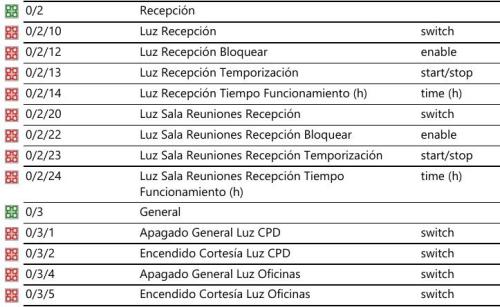
Said the above, we're going to the matter at hand. The Main Group Address Range for lighting is 0, the Middle Address Group Ranges are:
- 0 for CPD (Data-centre), so to identify CPD lighting we will use 0/0/x as Group Addresses
- 1 for offices, so to identify offices lighting we will use 0/1/x as Group Addresses
- 2 for reception, then to identify reception lighting we will use 0/2/x as Group Addresses
- 3 for general lighting (CMI, master control) we will use Group Addresses in the form 0/3/x
You can see below image captures of the Group Addresses report generated by ETS for the lighting, showing the DPT used in them.
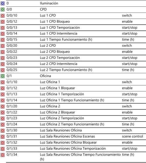
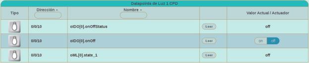
Looking at how Comm. Objects are linked to Group Addresses, we can say that 0/0/10 is linked to 3 Group Objects in ETS and has 3 Datapoints in Domorela. As you can see below, 2 of them are onOff and onOffStatus referring to switched control and status, while the third is oML[0].state_1 used by CMI to know if there are lights switched on to perform a general switch off, or if all lights are switched off to perform a switch on of the complimentary lighting. Note that some Datapoints are showing controls and other not, you can refer to a former configuration article in the Blog to know why.

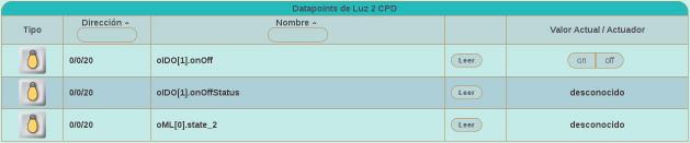

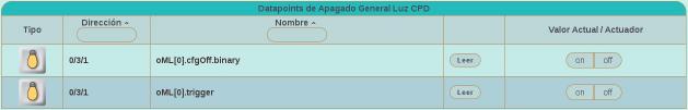
If we look at Luz 2 CPD above we will see this third Datapoint is oML[0].state_2, which is also a Comm. Obj. for CMI in the ALLinBOX. These oML[0].stateX objects are used internally by ALLinBOX CMI to switch off if any of them is "on". In order to simulate this feature in Domorela DMRL1 we need also link onOffStatus objects to 0/3/1 Group Address in the ETS project, appearing Group Address 0/3/1 as Receiving Address in onOffStatus objects. This way, when the project will be imported into Domorela configuration, Luz 1 CPD and Luz 2 CPD will be switched off when the CMI Group Address 0/3/1 is put to off. Note that linking onOff (Encender/Apagar) objects to Group Address 0/3/1 is not needed when operating within a real environment because switch off is done internally by ALLinBOX.
Reading the above you can conclude that Domorela behaviour while operating in simulation mode is to update objects through Receive Addresses configured in ETS project, but only add Datapoints to his Send Group Address. So is possible to update different Group Addresses from another Group Address having any of his Datapoints linked to the update Address as one of his Receive Group Addresses. This is the normal behaviour in KNX. Here we use this behaviour to simulate internal operation of CMI in the ALLinBOX device that switches off all outputs, thus avoiding the need to use Receiving Addresses.
Now we'll explain how Domorela will work with the time objects that serve to store the uptime for all the light objects. These objects are stored in Domorela's Configuration as Addresses with a single Datapoint of Integer type, according with their DPT in the ETS project.
![]()
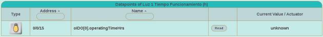
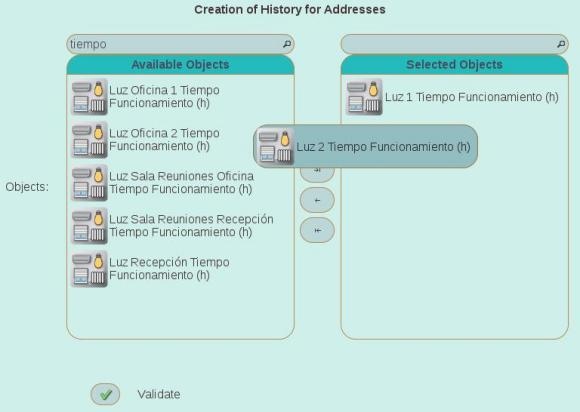
They will be configured as Histories to allow Domorela periodically save their values as historical series and show their values as Graphs. Below you can see how easy is to find these objects in the Configuration View after a good naming strategy in the ETS project.
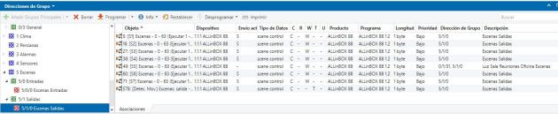
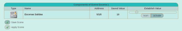
Finally, we will configure Scenes in Domorela in order to simulate the ones defined in the ETS project to switch lights when motion detection controls of ALLinBOX 88 detect movement. As you can see below, there are in use scene objects for each output storing DPT 18.001 (scene control) values and outputs are parametrized with different scene numbers in order to properly switch them to on or off value.
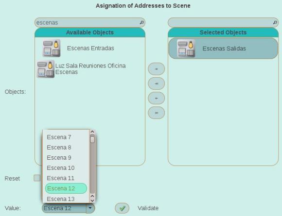
Domorela can be configured with a set of scenes implementing all the possible values that the corresponding Address Group linked with the output scene objects, in this case 12 scenes configured with next values: activate 10, activate 11, activate 30, activate 31, activate 40, activate 41, activate 50, activate 51, activate 60, activate 61, activate 62, activate 63. This also can help to check ETS configuration to avoid any mistake before the installation.
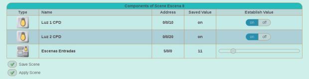
An alternate configuration could be to define the scenes with Adresses corresponding to each of the outputs, i.e. lights, controlled by the ALLinBOX 88. Then they will look like below image, which could be more clarifying to many people than the above one. Below, the scene is showing the case of detection is on and switching on lights, so scene value is 11, while the above image shows scene being set to 10, when detection pass to off value and is switching off the lights.
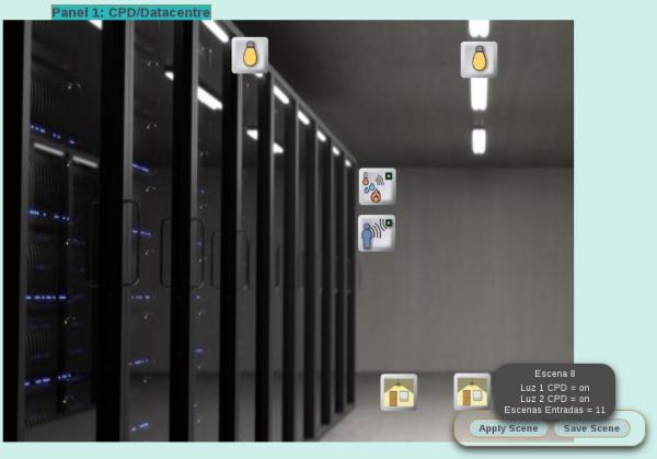
In order to simulate you can include the scenes in the corresponding Panel View and click over Apply Scene control of the scene widget, as is shown in the below image1, were you can see next elements ordered from top to down: Luz 1 CPD, Luz 2 CPD, Sensor Movimiento CPD (presencia), Alarma CPD intruso and the Scene controls.
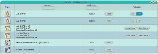
If you wish you can change the view mode of the Panel View and see all the elements in a table with all their controls.
Next article will talk about HVAC configuration in the Lab.
