


")
")
")
")
Domorela's Blog: Modbus integration in Domorela (II)
In the past article we explained how Modbus elements, Datapoints and Slaves, can be configured in Domorela jointly with the KNX elements: Addresses, Datapoints and Devices.
In this article we explain how the users can visualize Modbus elements in the different Views of Domorela's WUI.
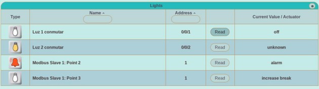
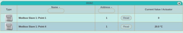
Going to the Elements Views, Modbus Datapoints will also be shown jointly with the KNX Addresses or KNX Datapoints (depending of the operation level used), as you can see in the below images.
Going to the Scenes View1, KNX Addresses and Modbus Datapoints are shown together in the Scene, can be parameterized within the scene, scene values can be saved and scene can be applied normally.
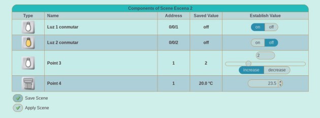
1 the difference between Scene View appearance on the referenced article and present one is because the former is from beta version
Is also possible to examine all the Modbus Datapoints present in a Modbus Slave in the Salves View in the same way we examine KNX Datapoints in a KNX Device.
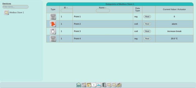
Note in the above image that is possible to handle Modbus DPTs as KNX DPTs. You can only do this in the case of Modbus data values are a subset of a set of KNX DPT values, or in the case their computational values are of the same type and range. Lets look below how it works in the shown Datapoints of the above image.
Point 2 is single bit coil, math binary values are 0/1 and boolean oBIX values are true/false. As the object represents an alarm you can configure the Modbus Datapoint with DPT equal to KNX DPT with value 1.005, which corresponds to no alarm/alarm values.
Point 3 is a 16 bit register representing Real values of Temperature in Celsius degrees, so is possible to configure its DPT as the KNX DPT with value 9.001. By doing this Domorela will display the corresponding values of Temperature and unit of measurement.
Next article will show Modbus elements integration in Panels and Graphs.
