Domorela's Blog: Virtual Lab with Domorela DMRL1: HVAC configuration
As we told in the second one of this series of articles, we included in our Virtual Lab 3 HVAC thermostats to control ambient temperature in the 3 locations included in the ETS project: the CPD (Datacenter), the offices and the reception. These thermostats are linked to 3 of the inputs of the ALLinBOX 88 in order to take value of a temperature probe connected to them, so we need one of the ALLinBOX inputs to control each thermostat and each thermostat can control one or two HVAC systems in the 3 locations. Domorela DMRL1 simulates them.
We remember here again the fact that we use Spanish language in ETS software so, in the project, all the references to ALLinBOX 88 inputs are written as En (Entrada n), all the inputs related to temperature are called as Temperatura, the ones related to HVAC controls are called as Control Clima in the case of cooling/heating system and Sistema Enfriamiento for cooling system. Note also that CPD refers to Datacenter.
Going to the Group Addresses structure, the Main Group used for HVAC is 1 and the Middle Groups use are, like in the lighting, assigned per location:
- 0 for CPD (Datacenter), so to identify CPD lighting we will use 1/0/x as Group Addresses
- 1 for offices, so to identify offices lighting we will use 1/1/x as Group Addresses
- 2 for reception, then to identify reception lighting we will use 1/2/x as Group Addresses
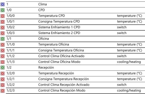
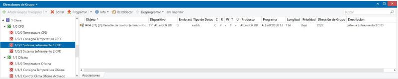
You can see below an image capture of the Group Addresses report generated by ETS for the HVAC, showing the DPT used in them.
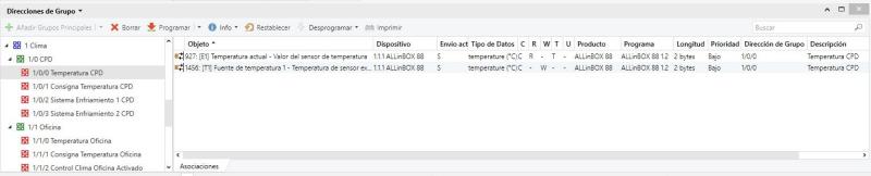
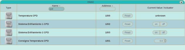
In the CPD, HVAC is composed of 2 cooling systems that are being controlled by a single thermostat with a two point control with hysteresis that will also use a mechanism of protection to avoid overheating and overcooling, so we need to parameterize ALLinBOX with 4 control points for temperature, a setpoint temperature and take the current temperature from their corresponding temperature probe.
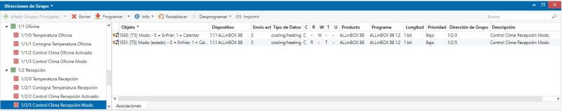
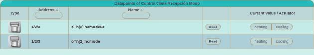
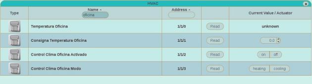
In the offices an reception, HVAC is composed by a single cooling/heating system controlled by a single thermostat with the same type of control and protection as in the CPD.
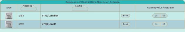
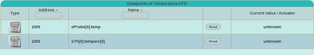
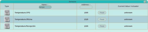
We will configure Addresses corresponding to temperature probe inputs first as sensor and after as HVAC, this way we include them in their corresponding Elements Views: first in the Sensors View and after in theHVAC View. Note that the icon shown is the one of the last applied contract, HVAC in this case.
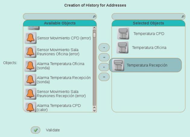
Also we will create Histories for temperature probe inputs, in order to measure them along time and to show them as Graphs. In the case we want to allow the users stablish the setpoint temperature, we could even create Histories for setpoint temperatures in order to know if the users are making a good use of the HVAC system.
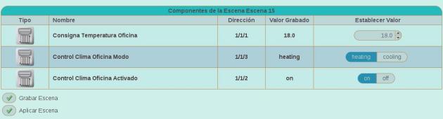
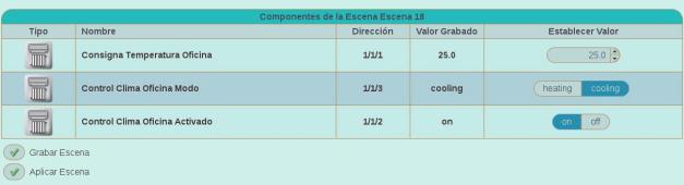
In order to simulate HVAC behaviour with Domorela DMRL1, we can create Scenes for each of the setpoint and control temperatures aimed to switch cooling/heating mode, swicth on and switch off the CPD's cooling system. They will include temperature probe, i.e. input values, and thermostat controls, i.e. output, values. To complete simulation is possible to send periodically scene and temperature probe values through Domorela's REST API to force value changes and to have historical records of temperature with random data. We'll see how to do it in later articles talking about testing the Virtual Lab.
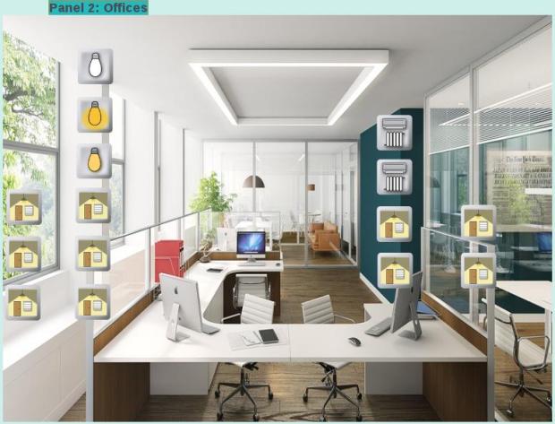
And we can include them in the Panel View of each one of the HVAC zones. Here you can see the one corresponding to Offices, that is also showing lighting elements and scenes.
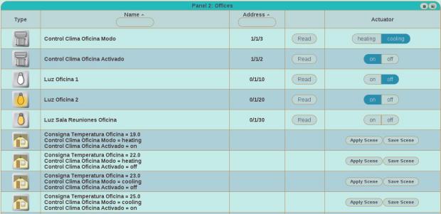
Remember that if you wish you can change the view mode of the Panel View and see all the elements in a table with all their controls.
Next article will talk about alarm configuration in the Lab.